Step 10 - Final Wiring
It's time to fix the loose ends.
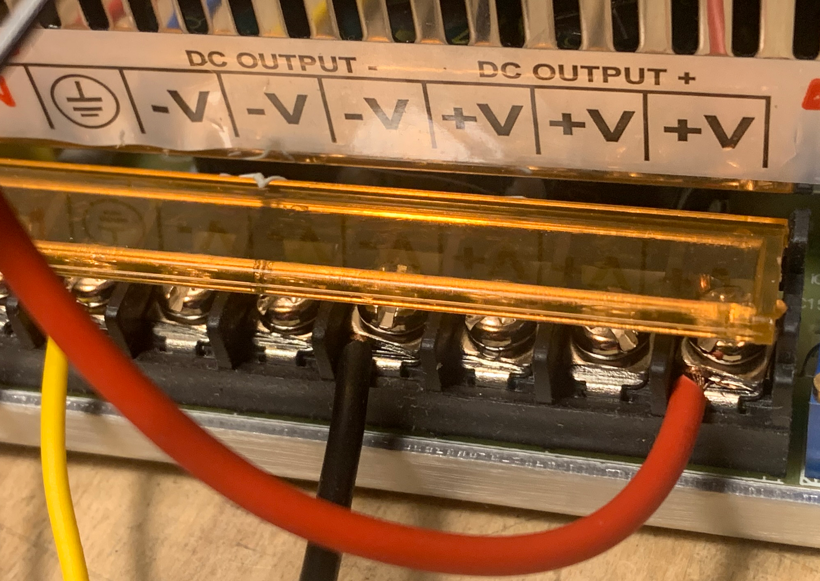
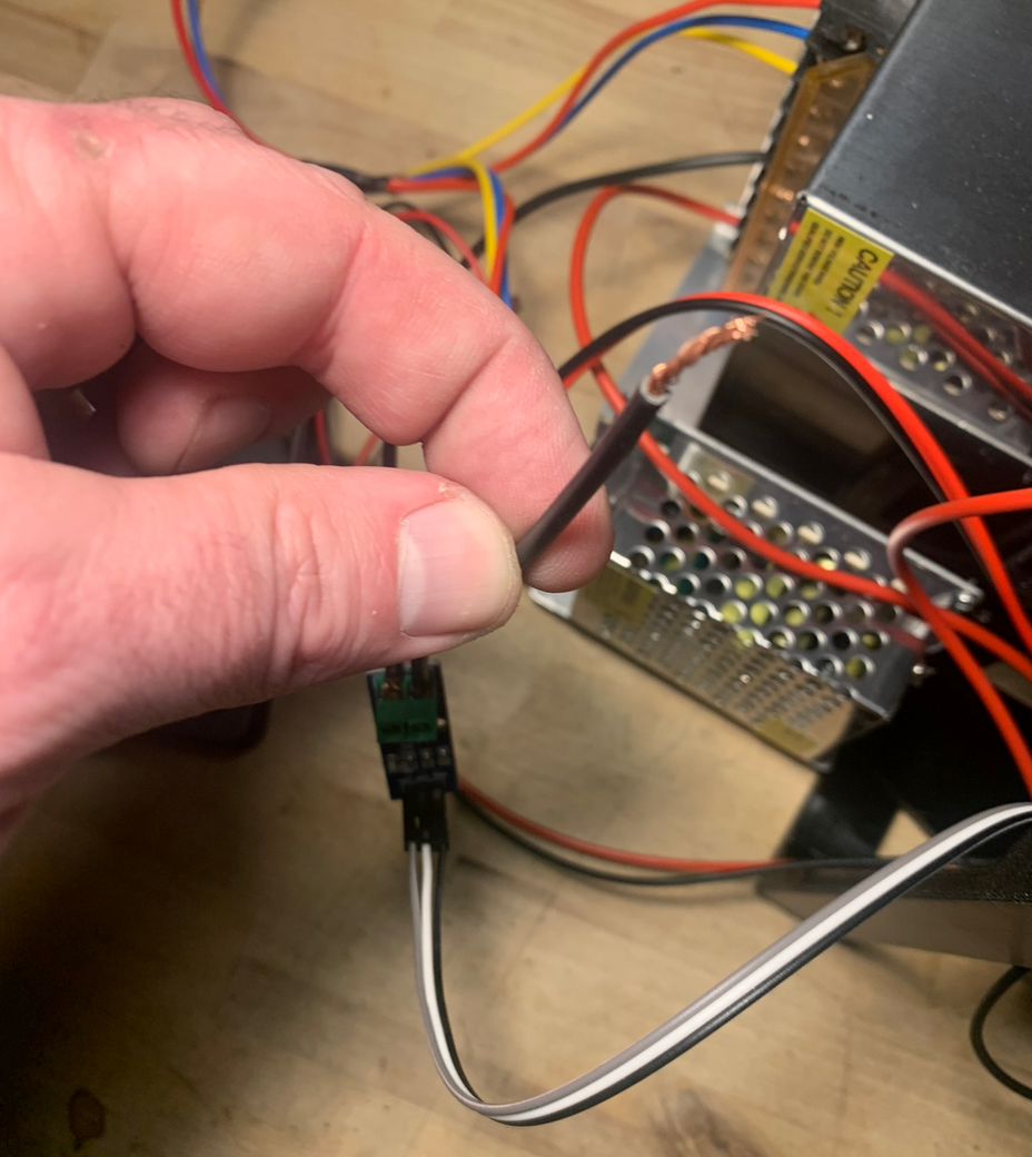
First we'll connect the thick red wire going out from + on the output side of the SSR to one of the + terminals on the 48V power supply. Twist the leads before attaching to ensure good connection.
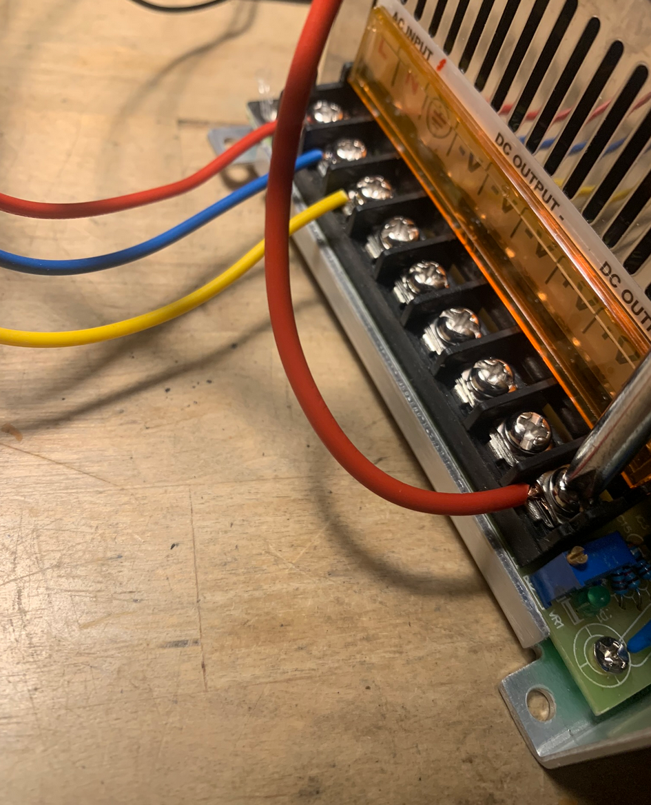
Caution: As mentioned before the terminals can have different order/location on power supplies, so make sure the terminal is marked with + and do not just connect the wire as shown in the picture.
Connect the long black wire from the cureent sensor to one of the - terminals of the 48V power supply. Twist the leads before attaching to ensure good connection.
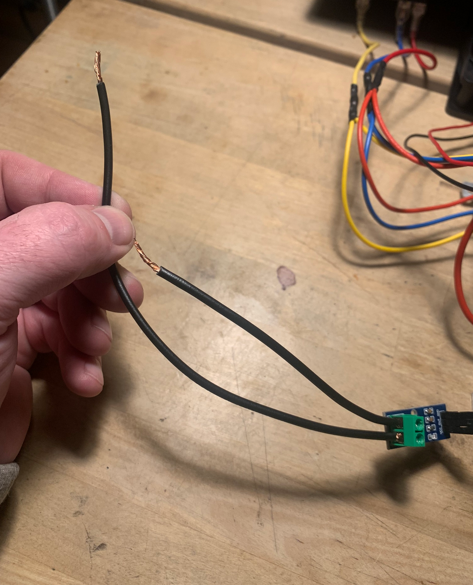
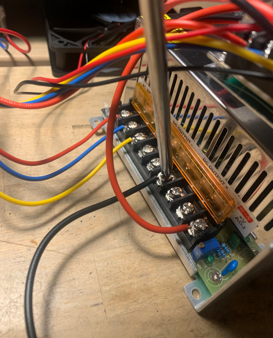
Caution: As mentioned before the terminals can have different order/location on power supplies, so make sure the terminal is marked with - and do not just connect the wire as shown in the pictured.
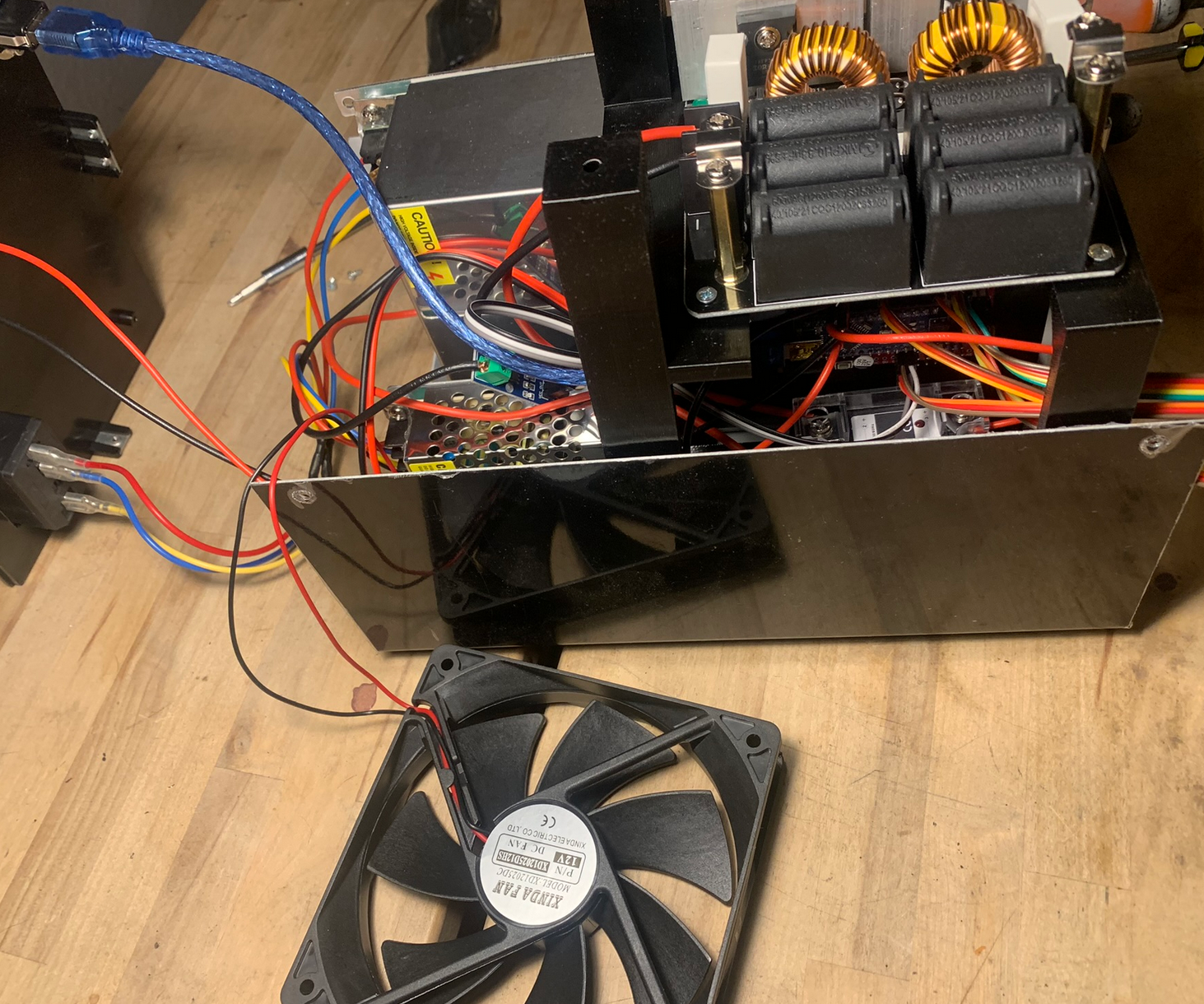
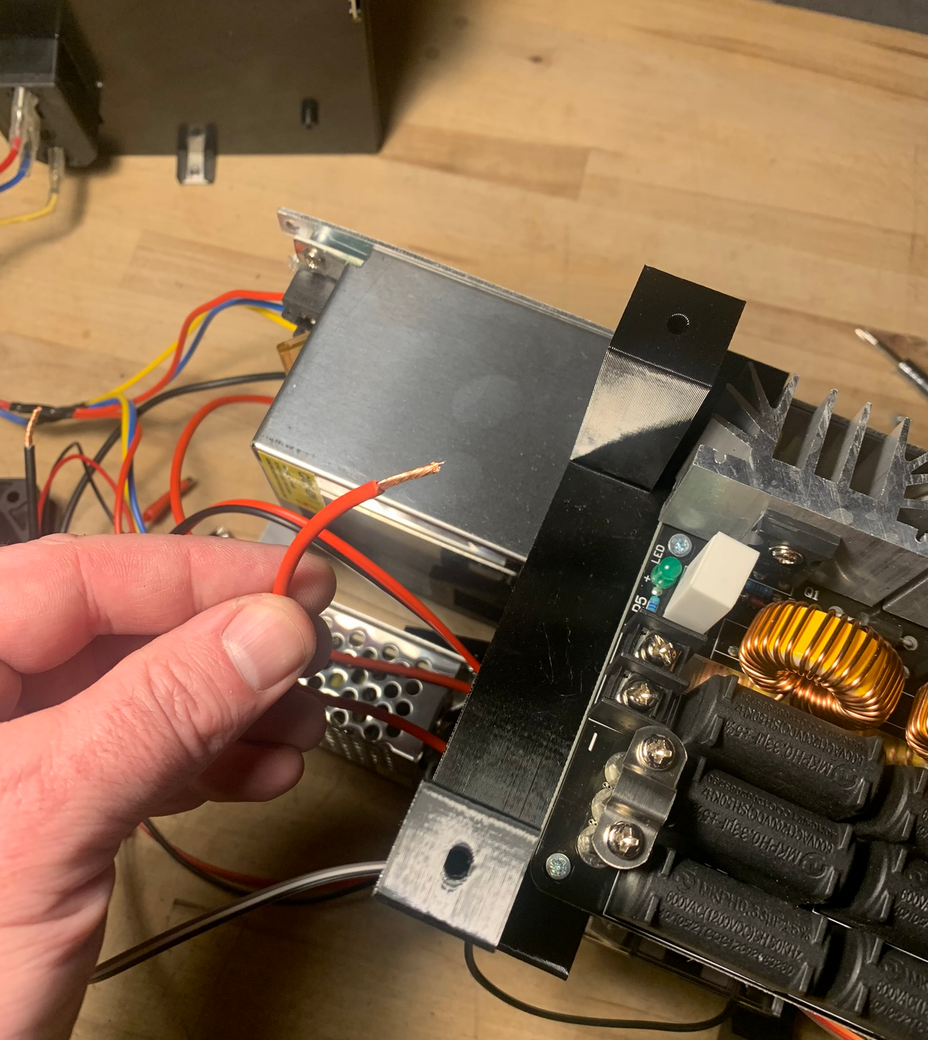
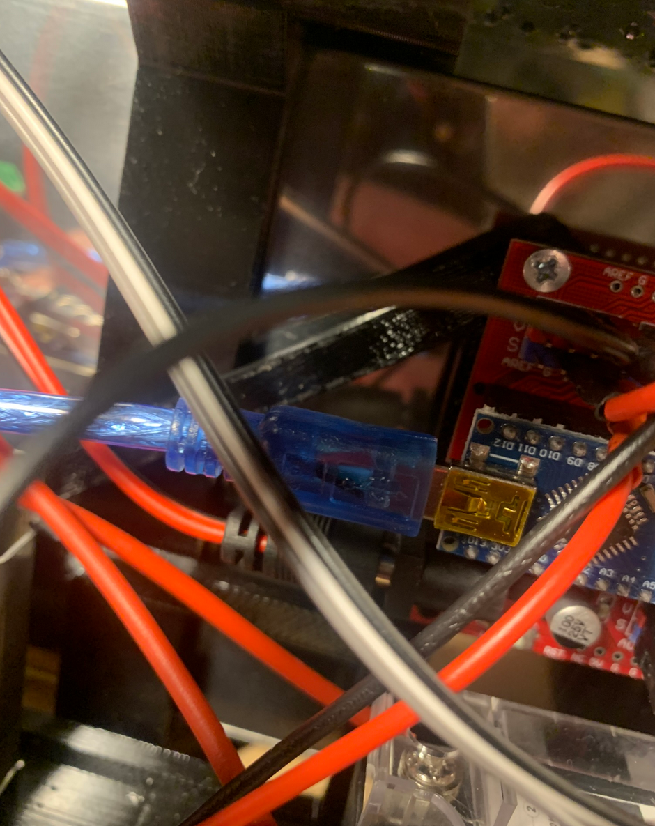
Time to mount the ZVS board.
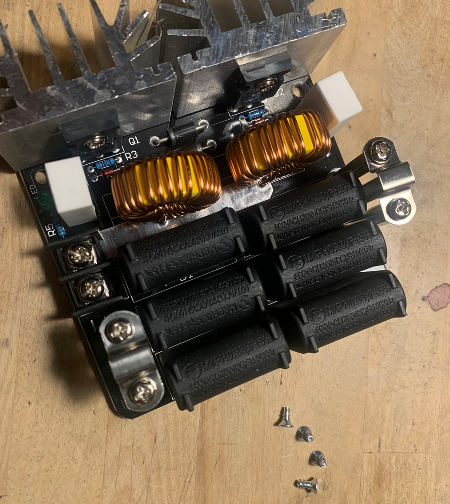
Place the ZVS board on top of the brackets and position it so it's oriented as shown in the picture below and the mounting holes match the holes in the brackets. Secure it using 4 small tapping screws.
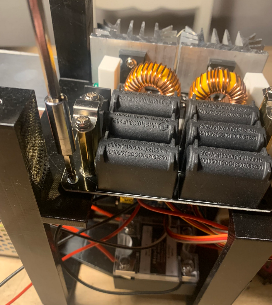
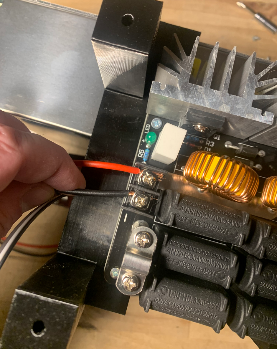
Attach the red thick wire going from - on the output side of the SSR to the + terminal of the ZVS board. Twist the leads before to ensure good connection.
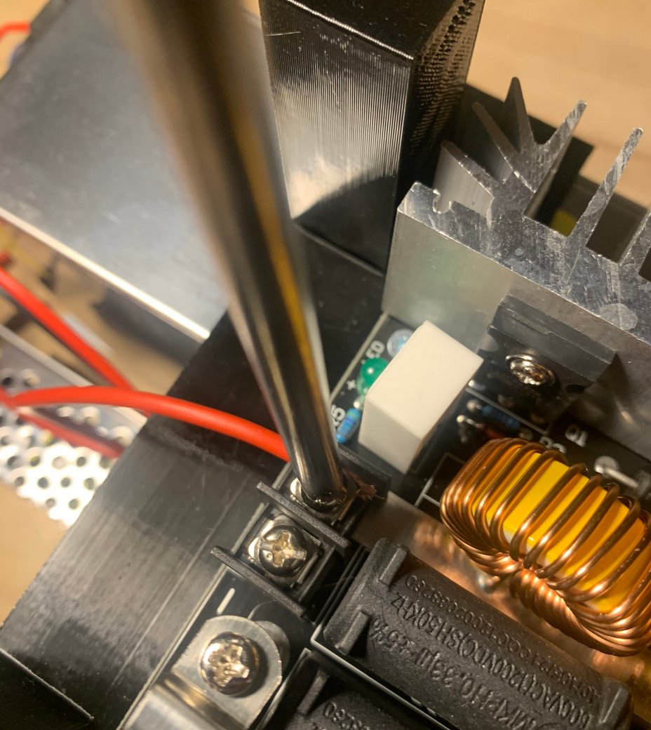
Attach the thick black short wire going from the current sensor module to the - terminal of the ZVS board. Twist the leads before to ensure good connection.
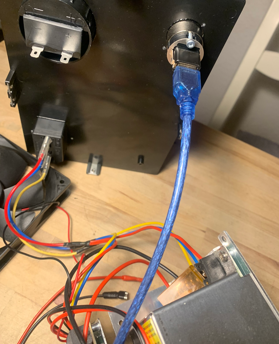
Connect the USB socket on the controller board to the USB socket on the enclosures rear using the provided USB cable.
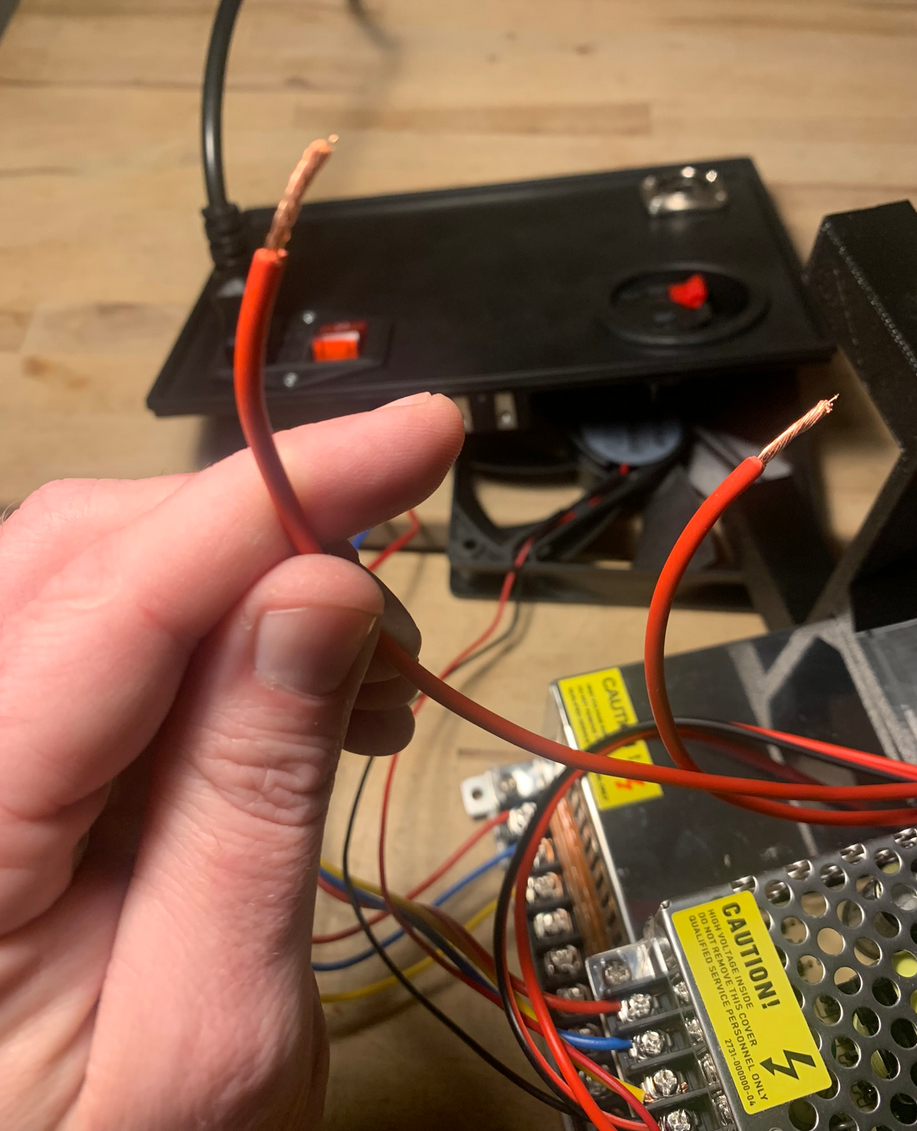
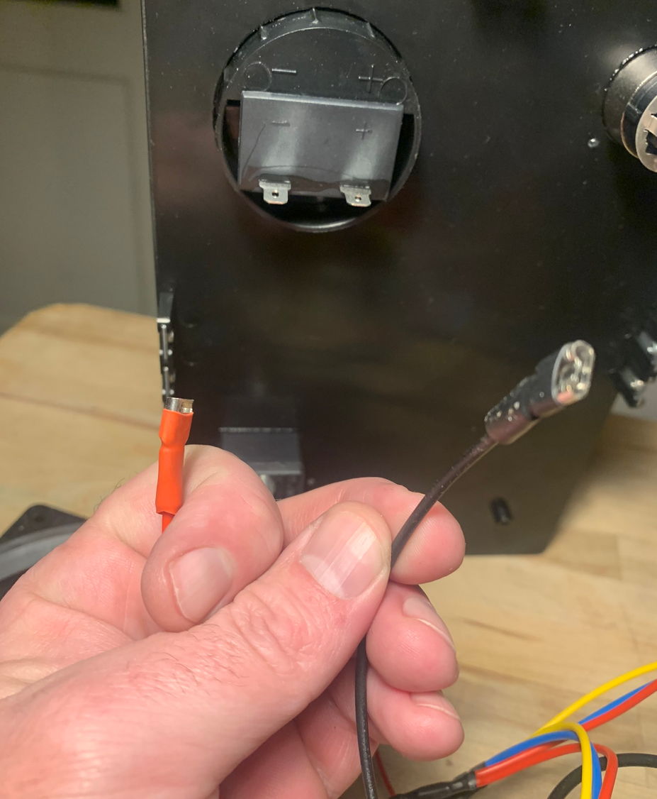
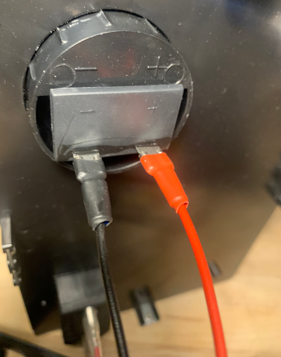
Finally attach the red and black auto feeder signal wires to the "loudspeaker" terminals. Red goes to red and black goes to black.
Now all wiring is practically done. Power is being provided to the ZVS board, but we have not attached a coil yet, so DO NOT turn on the machine. Starting an annealing cycle without a coil will DESTROY your ZVS board.