Step 5 - Connecting the Rotary Encoder/Decoder
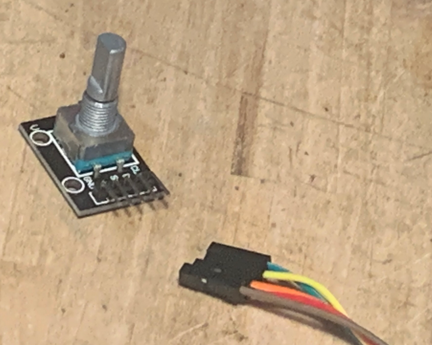
The rotary encoder/decoder is connected to the controller board using the 5 lead connection cable.
Make sure the power is off and no connection to mains is made.
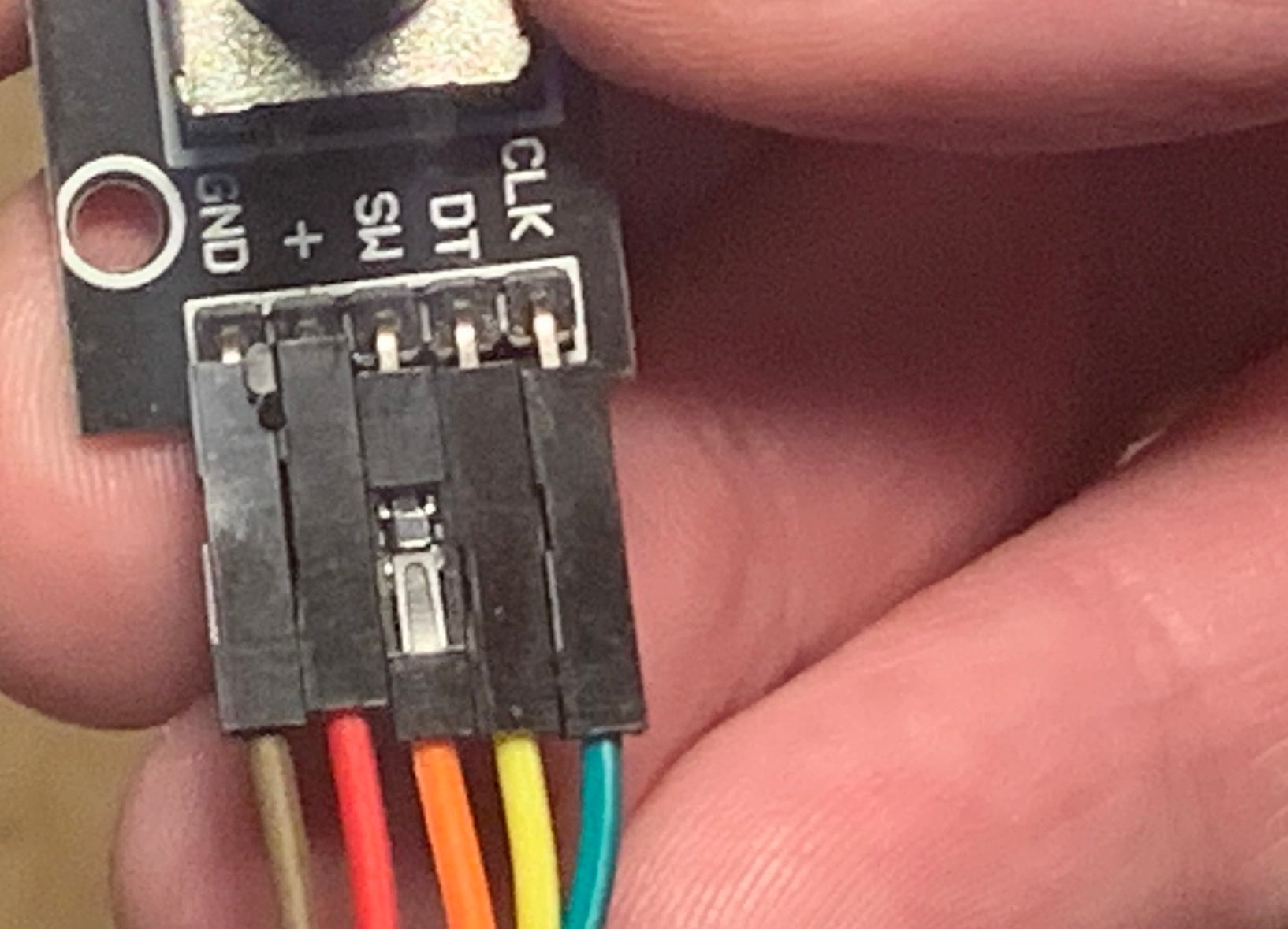
Connect one end of the cable to the encoder/decoder as shown in the picture below.
Brown connects to GND, Red connects to +, orange connects to SW, yellow connects to DT and green connects to CLK.
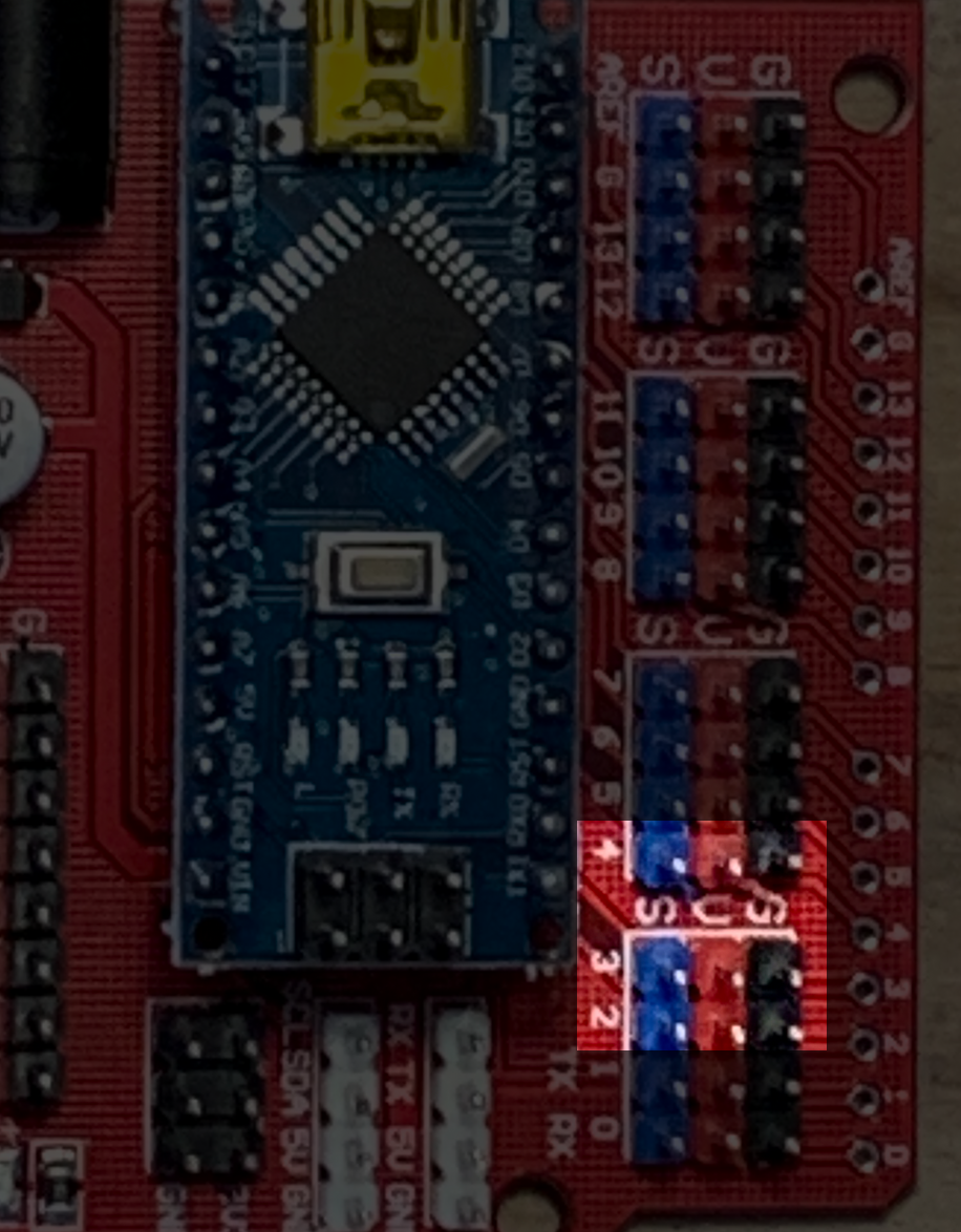
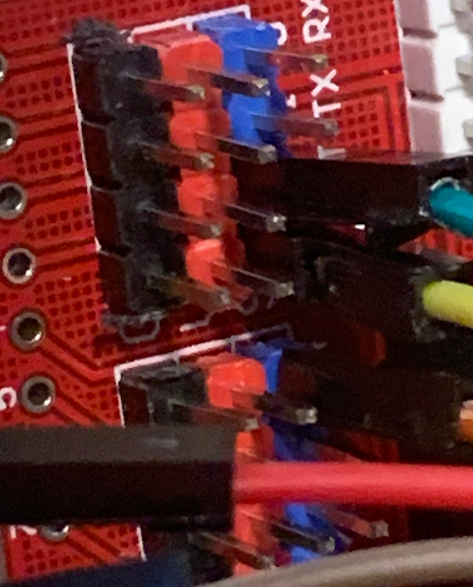
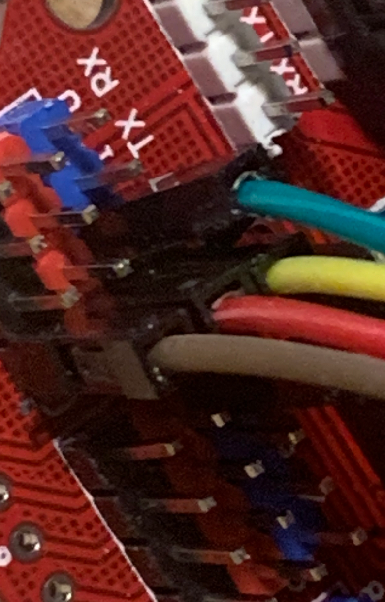
Identify the digital pin headers on the controller board.
Green wire (CLK) is connected to digital pin 2 (the blue connector pin), the yellow wire (DT) is connected to digital pin 3 ( blue pin) and the orange wire is connected to digital I/O pin 4 (blue pin).
Red wire is connected to one of the red pins (V) next to the aboe, and the brown wire is connected to one of the black pins (GND) mentioned above.
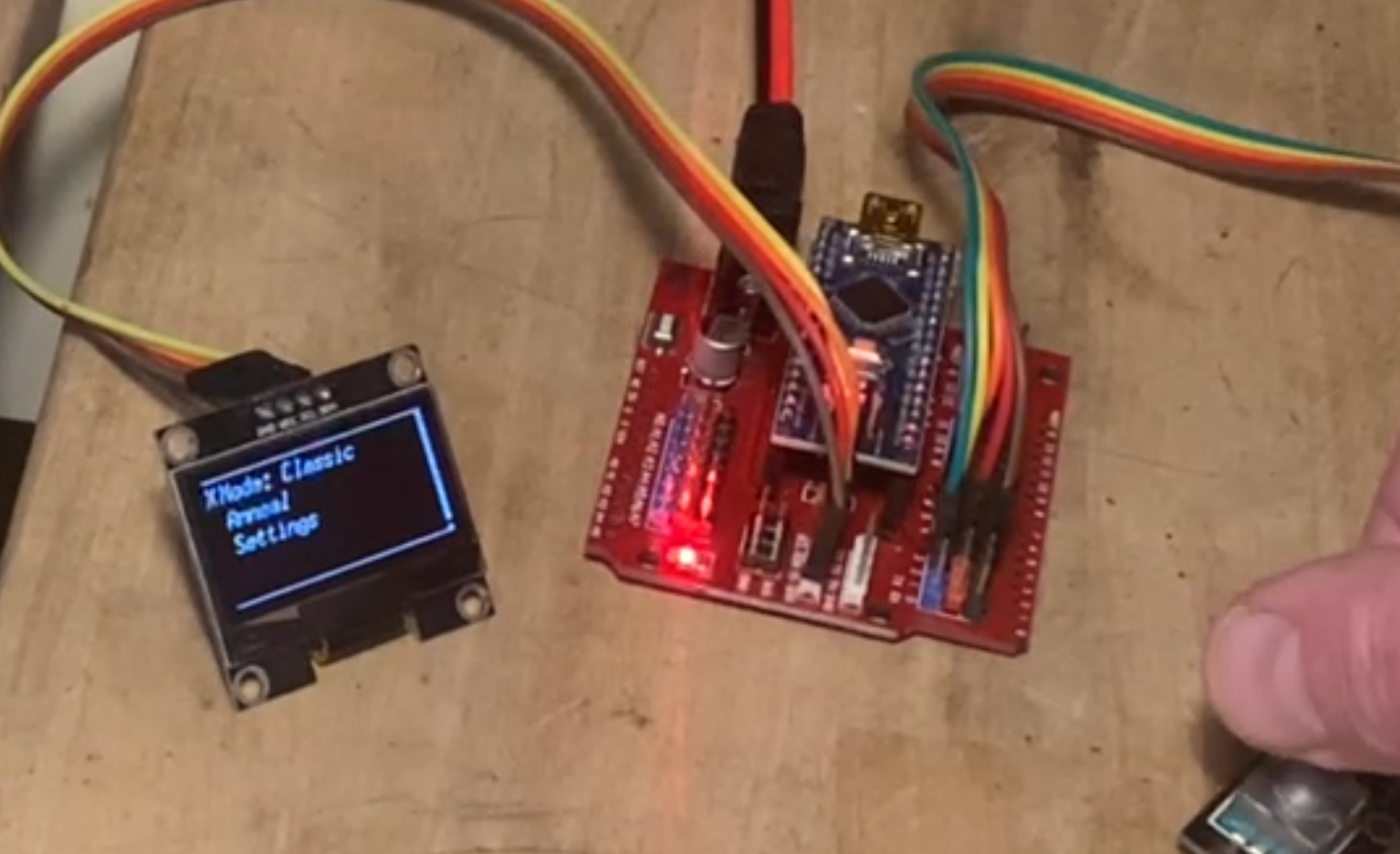
When everything is properly connected, turn on the power. You should be able to navigate the menu shown using the encoder by rotating and pressing the shaft.