Step 9 - Final Connections to the Controller Board
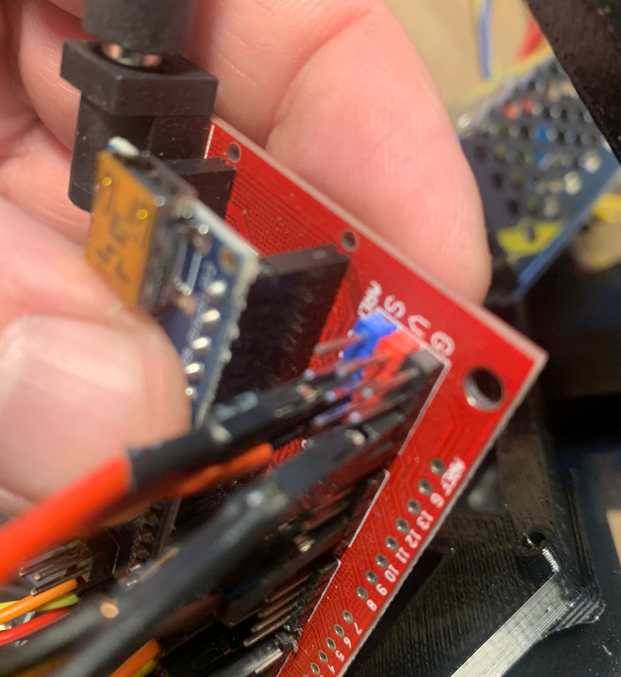
Find the feeder signal cables in the kit.
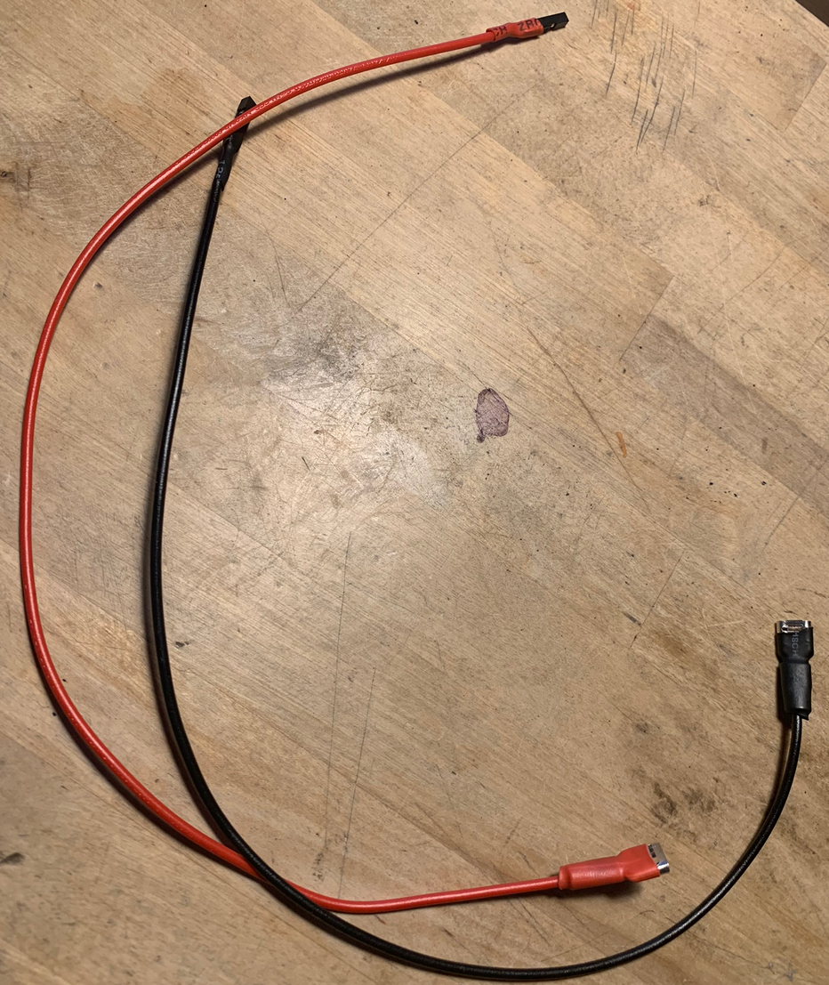
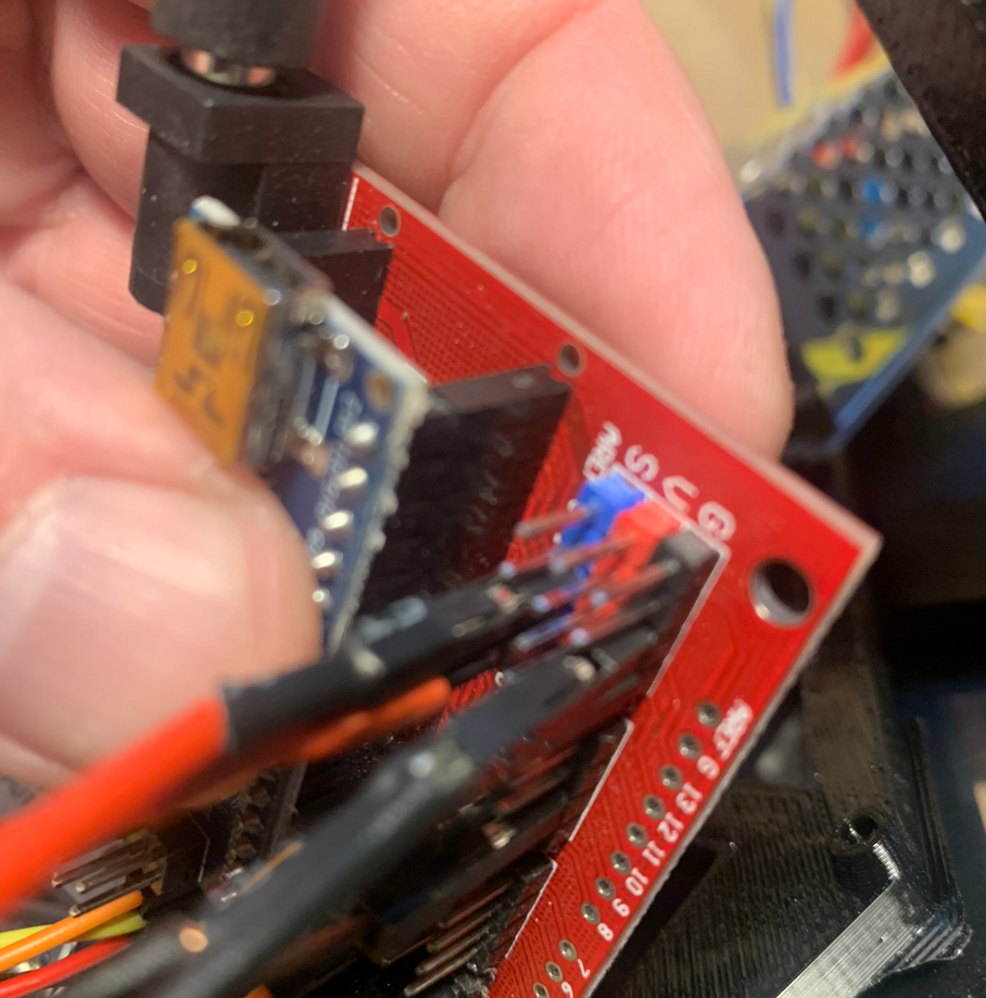
Attach the red wire to the the blue pin for D12 (S). Attach the black wire to the black pin (G).
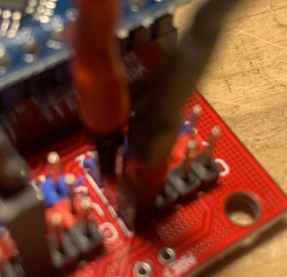
Attach the red wire connected to the input side of the SSR to the blue pin for D13 (S). Attach the black wire connected to the input side of the SSR to the black pin (G).
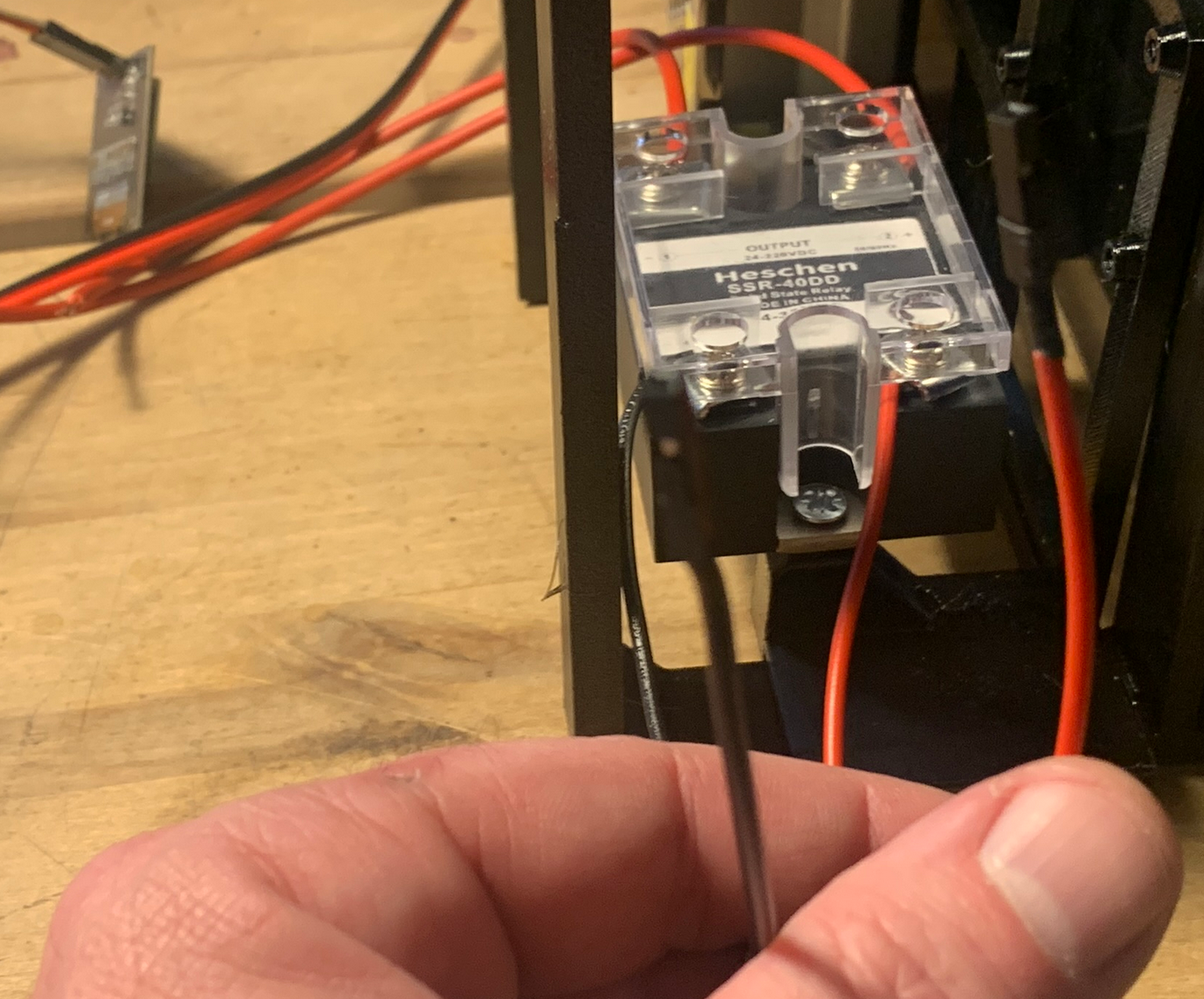
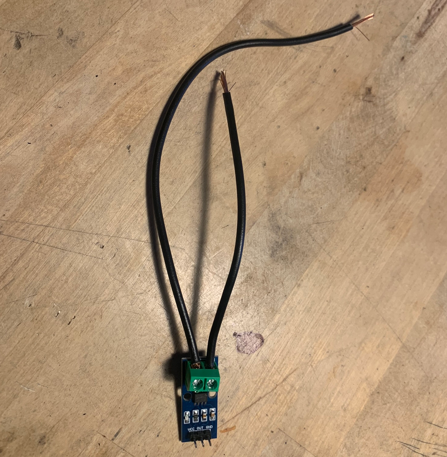
Last we need to connect the current sensor to the controller board. Before we do that, we need to connect the 2 thick wires to it.
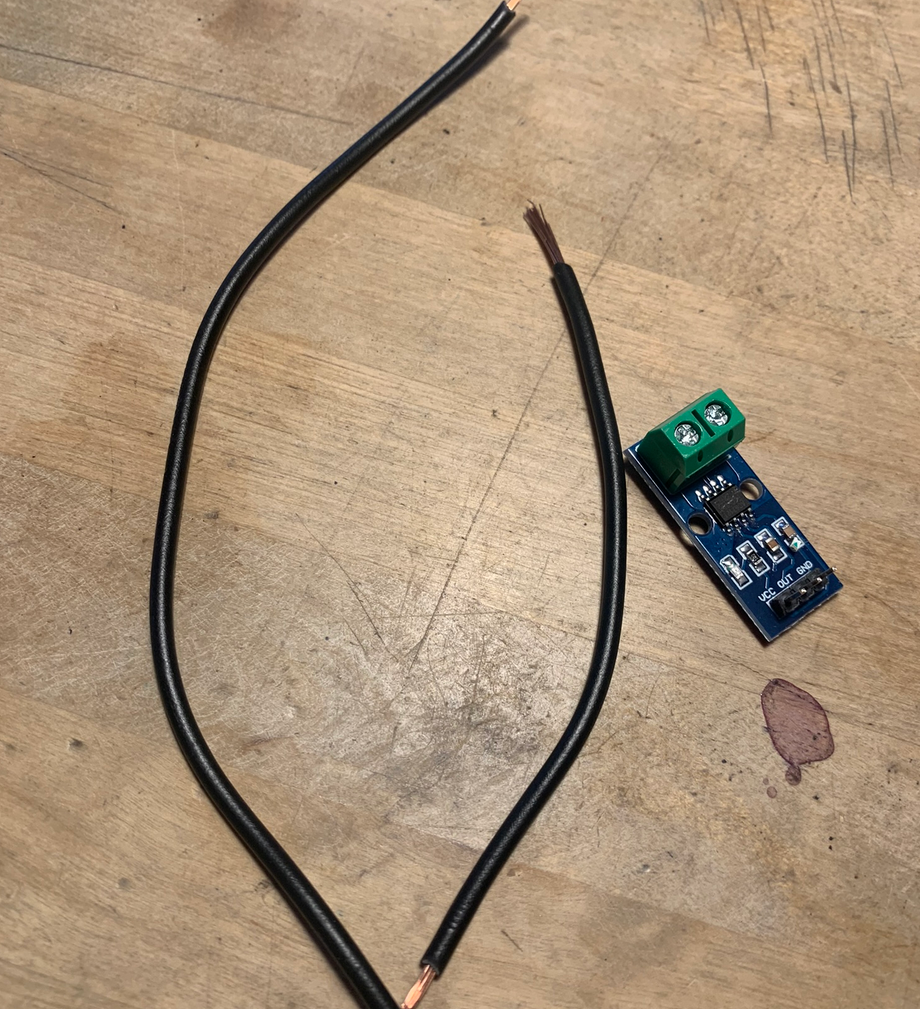
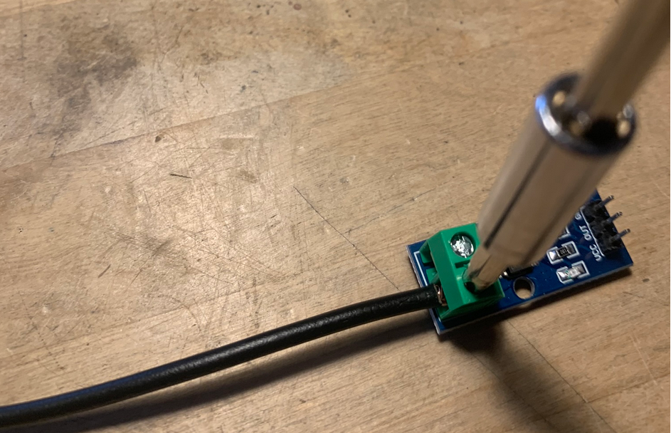
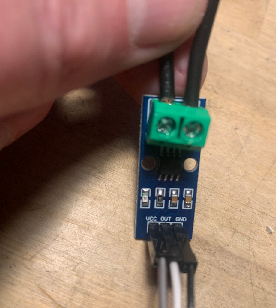
Fasten the longest of the 2 black wires in the lower screw terminal (looking down on the current sensor with the screw terminals facing left). The shorter wire is fastened in the upper screw terminal.
The current sensor is connected to the controller board using the 3 wire connector cable (black, white and grey).
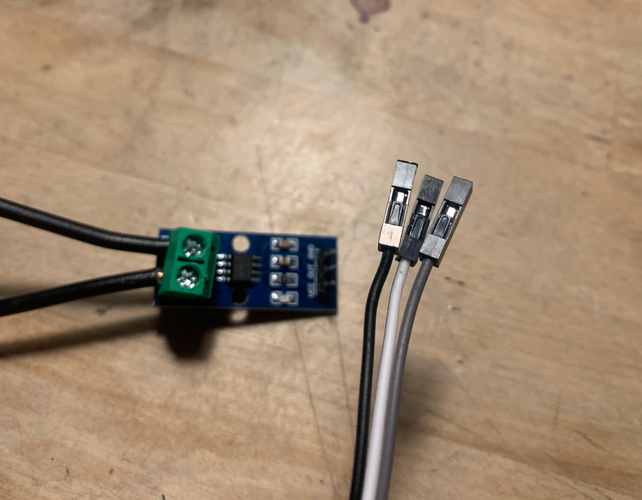
One end is connected to the current sensor. Gray wire connects to VCC, white connects to OUT and black connects to GND.
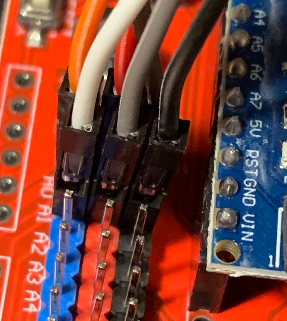
The other end of the cable is connected as follows: White is connected to blue pin at A1 (S), grey is connected to red pin at A1 (V)) and black is connected to black pin at A1 (G).
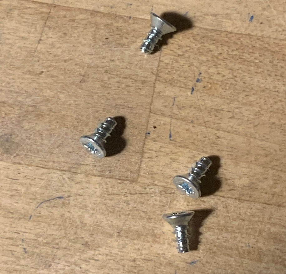
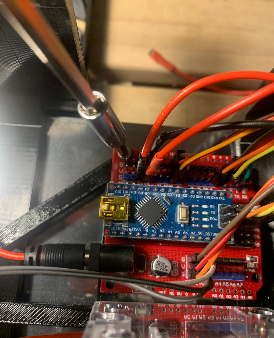
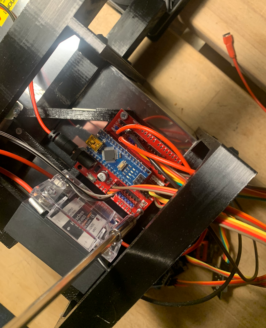
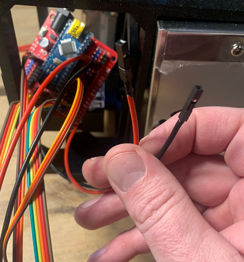
Now all connections have been done to the controller board it's time to secure it in place on the brackets using 4 small tapping screws.
Be careful not to pull out any connectors while "wiggling" the board in place. It's a good idea to put the wires going forward (servo, display, rotary encoder and vibration sensor) through the brackets first. And make sure the wires to current sensor and feeder terminals go to the rear.